Breadboarding 101: Your Guide to Prototyping Circuits
Breadboards are an essential tool for anyone interested in electronics, from hobbyists to seasoned engineers. They provide a solderless platform for quickly building and testing circuits, allowing for easy modifications and experimentation. This guide will introduce you to the basics of breadboards and how to use them effectively.
What is a Breadboard?
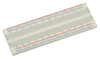
A breadboard is a rectangular plastic board with numerous holes arranged in a specific pattern. These holes are connected internally with conductive metal strips, allowing you to insert electronic components and connect them without soldering.
Understanding the Layout
- Terminal Strips (Power Rails): The long rows running along the top and bottom edges of the breadboard are called terminal strips or power rails. These are typically used for distributing power (+Vcc and Ground) throughout your circuit.
- Horizontal Rows: The main area of the breadboard consists of rows of holes connected horizontally. Each row forms a node, meaning all components inserted into a single row are electrically connected.
- Center Gap: A gap in the middle of the breadboard separates the two sets of horizontal rows. This gap accommodates integrated circuits (ICs), allowing their pins to connect to separate rows on either side.
Connecting Components
To connect components on a breadboard:
- Insert component leads into the desired holes. Ensure the leads are firmly seated.
- Use jumper wires to create connections between components. Jumper wires are insulated wires with exposed ends that plug into the breadboard holes, bridging connections between different rows or components.
Tips for Effective Breadboarding:
- Plan your circuit: Before plugging in components, sketch your circuit diagram. This helps visualize connections and minimize errors.
- Organize your layout: Keep your breadboard neat and organized. Use different colored jumper wires for different signals (e.g., red for power, black for ground) to improve readability and troubleshooting.
- Test connections: Use a multimeter to verify connections and ensure components are receiving the correct voltage and current.
Example: Simple LED Circuit
Let’s build a simple circuit to illuminate an LED using a breadboard:
- Connect the positive (+) leg of the LED to a resistor. Resistors limit current flow to protect the LED.
- Connect the other end of the resistor to the positive (+) power rail.
- Connect the negative (-) leg of the LED to the negative (-) power rail.
Once connected, your LED should light up! Experiment with different resistor values to change the LED brightness.
Pro Tips:
- Power Supply: Invest in a reliable power supply with adjustable voltage and current limits to suit your project needs.
- Component Organization: Use a component organizer to store and easily access your resistors, capacitors, transistors, and other electronic parts.